Flat Fields and Stray Light in Amateur Telescopes
(The Ugly Truth – Its more Complicated than you ever thought!)
A lot of users struggle with flat fields that don’t work well, and leave gradients in their images, or hot spots, or other hard-to-process-out artifacts. As a result they have resorted to twilight flats and other techniques to get better results. In this paper I will reveal the real source of the problems, discuss why twilight flats are not very good, and outline some tips for better results. I believe even those users who think they have mastered the flat-fielding technique still have problems they do not recognize.
To begin – many black surfaces are not
I have constructed a flat field system at home where I can use LEDS of different colors to take a really good flat field with our CCD cameras, and telescopes. It is nothing more than multiple LEDS of different wavelengths, and a large pasteboard box painted black on the inside, with apertures sized to recreate an F/6 system. In Figure One I show flat fields collected using an expensive refractor any of you would be proud to own, using green light and near IR (940 nm) light. There is no vignetting whatever in this system! What looks like vignetting at the edges is actually excess light in the center of the image that has glinted off the coupling tubes near the camera. The donut appearance in the IR is due to these same glints.
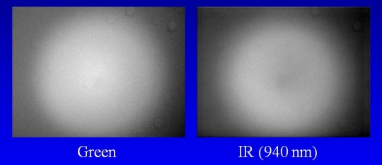
Figure One: Flat Fields with an Expensive Triplet Refractor
The center to edge variation here is about 6%, which would require flat fielding in an astro-image. The problem is light pollution for most people means that their sky at night is a greenish yellow color, but if they took a flat field using a flashlight with an incandescent bulb, which has strong IR, the astro-images would have an inverse donut illumination pattern. There is another concern here. Many astrophotographers are doing photometry with their systems, and quite often compare two stars in different parts of the field to make their measurement (differential photometry). They would flat field their data assuming the pattern seen in the green image was vignetting, which means a sensitivity dropoff at the edges, but it is not. Sensitivity is actually constant to the edge. Figure Two illustrates this problem.
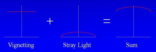
Figure Two: Stray Light looks Like Vignetting
This actually occurs with photometry. To properly map out the sensitivity of the image one must move a star around the field and measure its brightness at many places. Or, eliminate the stray light!
The stray light, particularly in the infrared, is usually caused by the manufacturer using black anodized aluminum surfaces in the telescope. Black anodized surface have about 50% reflectivity at 940 nm. Figure Three shows a number of “black” objects at 940 nm, as well as a white business card. You “see” the problem, literally. Truly black surfaces would be as dark as the interior of the nosepiece on the right side of the image.
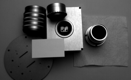
Figure Three: “Black” Objects at 940 nm
It is actually easy to see if you have some version of this problem. Take the camera out of the focuser position, point the camera at the sky or white surface, and look into the tube. Put your eye where the camera was. What you should see is the telescope aperture floating in a dark void. With the high end refractor of Figure One, I saw the pattern illustrated in Figure Four.
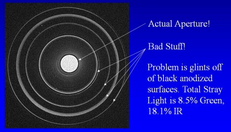
Figure Four: Looking up the Tube
As you can see, I had lots of glints off the coupling rings. I made a special camera for taking this image by modifying an ST-3200 to have a 6 mm F/12 focal length pinhole lens right in front of it. It was revealing, once again literally. Below I show the results for a Chinese Newtonian telescope. You can see the aperture and the secondary spider in the middle. However, that glow around it is 13% of the total light hitting the focal plane at 940 nm.
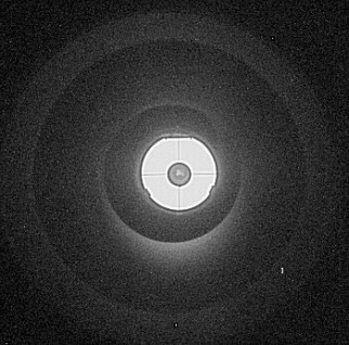
Figure Five: Chinese Newtonian
I know many of you are thinking “Why do I need to worry about this – the sky is dark?” The answer is, it’s not. You are pointing your telescope into a hemisphere of light. It may be dim, but so is what you are imaging. In fact, for the high end refractor, the fraction of the skylight that you want to hit the chip is only 1/7300th of the light entering the lens, and you want to knock down that unwanted stray light to the 1% level, or almost a million times total.
Now it is appropriate to delve into the science behind this problem. The stray light problem would actually flat field out fine IF the flat field light source were exactly the same spectrum as the night sky. However, this is not the case. In Figure Six I show the relative spectrum of several light sources, measured with an SBIG DSS-7. My night sky from my back yard is also included.
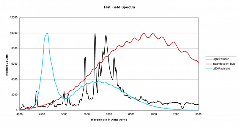
Figure Six: Spectrum of Typical Light Sources
A wavelength of 4500 Angstroms (450 nm) is deep blue, a wavelength of 5500 Angstroms is green, and 6500 Angstroms deep red. However, CCD cameras have sensitivity up to 10000 Angstroms (1000 nm), and the sky has about half its brightness, for a dark site, above 7000 Angstroms. In fact, the older imagers among you will remember the early days of CCD imaging when users marveled at the fact that moonlight was not a big problem for imaging. That was partly because it was a small fraction of the total skylight, which included the infrared. By the way, I have also measured the twilight spectrum, and it is a deep blue weighted spectrum, as one might suspect. It is a poor match to the night sky. Also, I have had some users that were flat fielding each color by itself to try to beat the flat field problem, and using incandescent bulbs turned down low. They were taking blue flat fields with orange light! That would work except most filters have some IR leakage, and when the IR content of the light is 100 times the blue, the leakage is as big as the desired light.
The other important part of this issue is that deep sky objects all have very low contrast against the sky background. Figure Seven shows a picture of the Horsehead Nebula captured by Tony Hallas with a luminance filter on a dark night from a good site. Note that the interesting features require detection of objects at the 1% contrast level, and world class work like Tony’s reveals features down to 0.2% and less. By the way, the brightness of areas of an astro-image are easily measured using CCDOPS Crosshair mode.
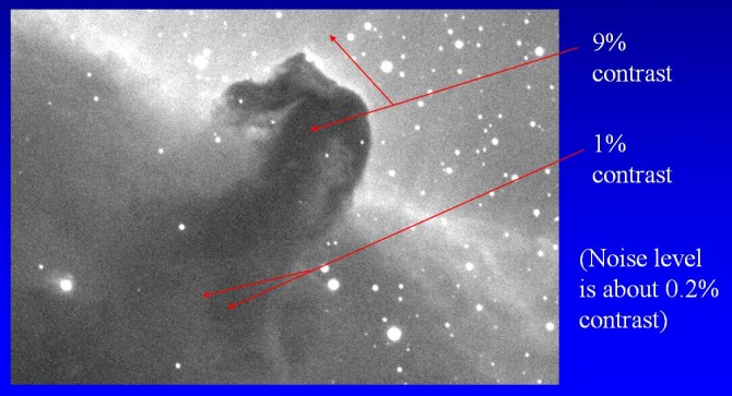
Figure Seven: Tony Hallas Horsehead, Luminance Filter
The Solution – Make Those Surfaces Black!
How to solve this problem – paint your interior surfaces! I have measured one paint that seems to work well, Rust-oleum Specialty High Heat Barbeque Flat Black spray paint. Others are no doubt good, but this one I know is flat, and has about 10% reflectivity in the IR. Avoid garden variety black paints since they may contain a dye, rather than a pigment. Many dyes common in the printing industry and elsewhere turn white at 700 nm. See the black felt in my previous image for proof. The Barbeque Black is good since dyes can’t take the heat, and the formulation uses a pigment. Remove the interior surfaces from any optical elements, and paint them well, masking the threads with tape. As an example of how well this can work, see Figure Eight below. The user was getting the flat fields shown on the left, and was convinced he had a defective camera, and wanted a new STL-11K. After many discussions, he painted the interior of his new focuser (a good brand, by the way) with flat black paint, and obtained the flat field on the right – problem solved!
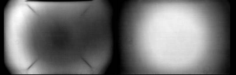
Figure Eight: Case History – Before and After Painting Interior of Focuser
It is also a good idea to use a light source for flat fields that is somewhat similar in spectral shape to the night sky from where you live. We hope that some company will take it upon themselves to make a hyperspectral flat field source using an array of LEDs with different center wavelengths to accurately reproduce the night sky spectral shape. SBIG has the equipment to measure the spectrum of the night sky or various light sources. Our DSS-7 has existed for many years, and our new ST-I Prism Spectrograph will be a valuable accessory enabling such measurements.
It’s Not Always Just Paint!
I may have led the user to believe that with a simple can of spray paint his problems are solved. As with most things in life, it is not quite that simple. I have made some effort to determine the limits of CCD cameras to detect low contrast objects, and have found that at the 1% level the CCD itself has spectral variations of sensitivity across its surface. Note Figure Nine, revealing bond wire glints. Light reflects off the gold structure and bond wires at the edge of the CCD, then reflects off the CCD cover glass, and produces this effect. Figure Ten shows a Single Shot color ST-8300 image of a galaxy from a light polluted sight with the contrast pushed, showing further evidence of the metallization changing the color of the sky background near the upper and lower images of the image. All of you reading this paper have this problem – check your images.
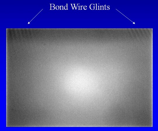
Figure Nine: Bond Wire Glints
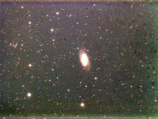
Figure Ten: Single Shot Color ST-8300 Image under Light Polluted Conditions
Sometimes the CCD itself has issues. Many of our users are pushing the limits, taking images from places like Tokyo or Beijing, where the contrast of deep sky objects against the night sky is 50 times poorer than what Tony Hallas deals with. An example of what can happen is shown in Figure Eleven below, a green STL-11K flat on the left, and a red STL-11K flat on the right. Note the cold spot in the center of the CCD in the green image becoming a hot spot in the red. A problem like this is hopeless to flat field, even with a hyperspectral flat field source. Unfortunately this chip is not considered defective by Kodak (now TrueSense). At the time of this user’s problem I surveyed a number of STL-11K cameras from our production line and determined that this was truly an unusual camera in the magnitude of this effect. However, all of them had variations at the 1% level, but not so prominently placed as the center of the CCD!
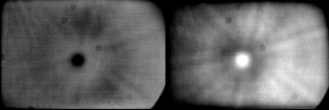
Figure Eleven: STL-11K Flat Field with Unusual Problem
Most amateurs take color images using the LRGB technique, where the L (luminance) image is painted with the color from the RGB images. There is some debate about whether one should use a clear filter, which passes all wavelengths, or a luminance filter, which blocks the infrared. Note the flat fields below in Figure Twelve, captured using the popular KAF-8300 CCD. A green flat is on the left, and looks quite smooth except for a dust glob. The flat field on the right is with an IR LED. Note the polishing marks on the right, which are revealed by the greater penetration of IR light into the silicon, the increased gradient left to right, and the grid structure becoming more prominent. Both images are displayed at the SAME 10% contrast full scale. This is a good chip!
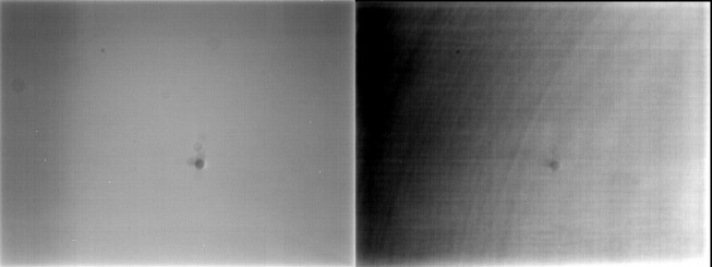
Figure Twelve: ST-8300 Flat Fields
By now you may be starting to feel CCD imaging is hopeless. That is far from the case. This last example merely illustrates the limitation of broad band imaging, and points out the importance of trying to match the flat field illumination to the night sky spectrum. For now I would recommend users take their “L” shots with a luminance filter to get more easily processed results. We here at SBIG are committed to improving what users can achieve with their equipment, and it is a continuous process. Tokyo or New York may be where you live! However, the more daylight we can shed on these mysteries of CCD imaging the more quickly solutions will be developed. I should note, though, that telescope suppliers need to pay more attention to baffling and flat interior coatings in their products. Many are good, but there are some very bad scopes out there. I will not name names in this paper. However, we may offer a short focus ST-I lens accessory soon that lets users make their own measurements.