Dual AFW Filter Wheel Adapter
$399.00 USD
This kit allows you to stack two AFW series filter wheels. It includes a two-piece adapter and a custom cable with three connectors, plus necessary screws.
The three main parts are:
- Bottom Dual Wheel Adapter. This is the thinner adapter plate.
- Top Dual Wheel Adapter. This is the thicker adapter plate.
- Three-connector cable. One connector has a custom back shell, which is thin enough to be mounted between the two wheels.
See Description below for an explanation of the installation procedure. Additional details are available in the AFW Filter Wheel Manual.
Product Description
Installation
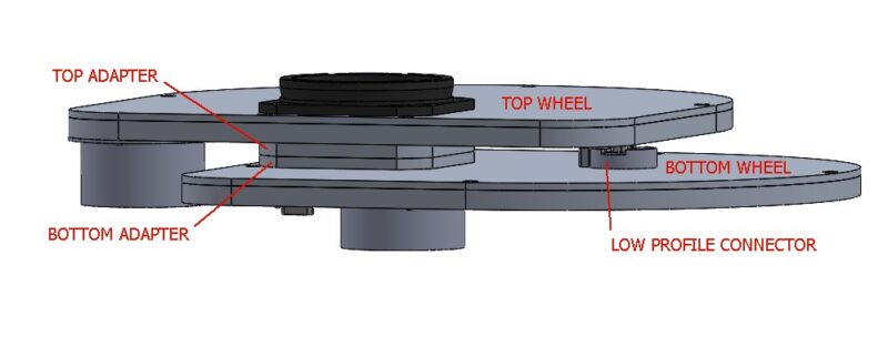
Refer to the diagram:
- Following the standard filter wheel instructions, remove the cover plate and mount the Bottom Wheel to the camera.
- Set the 1/2 selector at the edge of the circuit board to 1.
- Place the Bottom Adapter on the outside of the Bottom Wheel’s cover, with the four countersunk holes facing upwards. Use four 6-32 x 1/4″ screws to attach the adapter. When installed correctly the four screws will be inset into the adapter.
- Install filters and reattach the cover on the Bottom Wheel, per the standard instructions.
- Place the thicker Top Adapter on the Bottom Adapter, with the four countersunk holes facing upwards. Use four 6-32 x 1/4″ screws to attach it to the Bottom Adapter.
- Remove the cover from the Top Wheel.
- Set the 1/2 selector at the edge of the circuit board to 2.
- Using the supplied cable, attach the connector with the low-profile back shell to the Top Wheel. Orient the cable pointing inwards towards the adapters.
- The Top Wheel is now installed on top of the adapters, using the mounting screws that come with the filter wheel. Note that the Top Wheel must be rotated 90 degrees relative to the Bottom Wheel so that the motor cover does not hit.
- Install the filters into the Top Wheel, and reattach the cover. Attach the nosepiece adapter per the standard filter wheel instructions.
- Connect the second connector in the cable to the Bottom Wheel.
- Connect the third connector in the cable to the camera.
- Configure the MaxIm LT or MaxIm DL Pro software for the dual wheel. Please refer to the MaxIm DL user manual for details.
Filter Organization
The software setup will map each virtual dual wheel slot to a combination of slots in Wheel 1 (bottom) and Wheel 2 (top). As an example:
Virtual Slot 1 (Luminance) = Bottom Slot 1 (Luminance), Top Slot 10 (empty)
Virtual Slot 2 (Red) = Bottom Slot 2 (Red), Top Slot 10 (empty)
… etc.
Virtual Slot 10 (U) = Bottom Slot 10 (empty), Top Slot 1 (U)
Virtual Slot 11 (B) = Bottom Slot 10 (empty), Top Slot 2 (B)
… etc.
It is also possible to configure the Dual Wheel slots to use two filters together, if desired. As an example if you wanted to sometimes image very bright targets, you could include a neutral density filter in the top wheel that stacks on top of RGB filters in the bottom wheel. Please note that stacking two filters will result in a change in focus position compared to one filter.